 Tweet
Tweet
10-Mar-2008: First Draft.
11-Mar-2008: Red wire is Accessories, Ignition is Blue/Yellow. Thanks to eagle-eyed Chuck.
12-Mar-2008: Final pic of installation.
14-Mar-2008: Brief description of removing switch and faceplate + precaution to disconnect battery + orientation of ARB toggle switch
06-Apr-2008: As per Leachy's post, make sure the control circuit is fused.
This is the definitive guide to installing the ARB High Output On-Board Air Compressor - CKMA12 in a 2008 Toyota Prado GXL D4D. Let me know if I've missed something - I'll keep updating this post as needed.
The topics covered include:
Whilst the instructions that are supplied with the compressor are first-rate, they are generic. This is intended to focus on the idiosyncrasies of the Prado installation. The install vehicle is a 2008 D4D GXL.
Related threads:
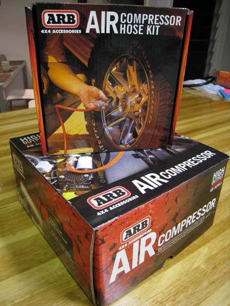
1. The Product
The price I paid was $280 for the compressor and $64 for the hose kit.
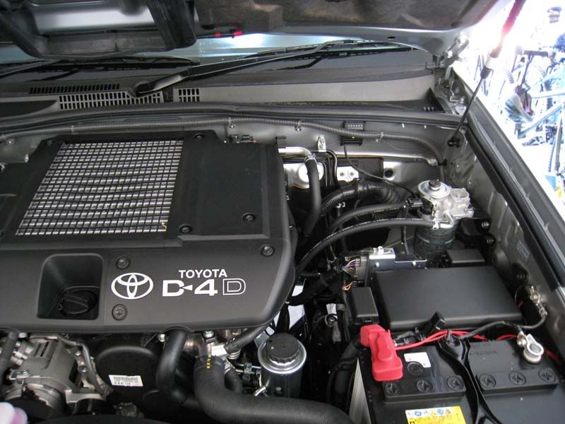
2. Locating the Compressor
Preferred location is the passenger-side, near the firewall and on the wheel arch.
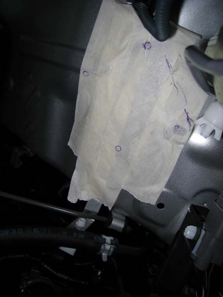
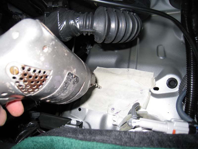
2.1 Masking Tape
Lay some masking tape to protect the paint-work and also to assist later with drilling.
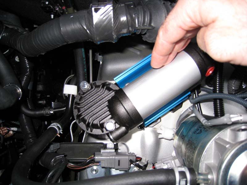
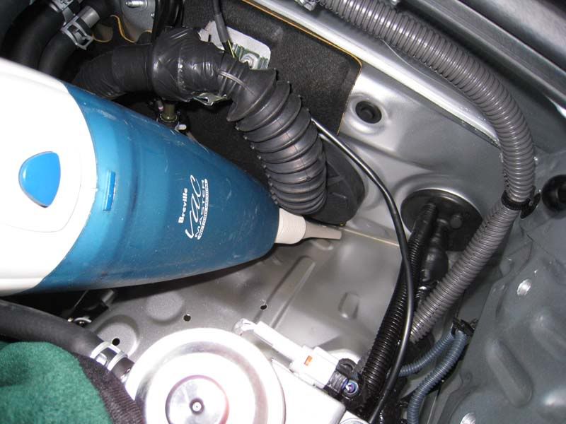
2.2 Orientation
This pump gets very hot, so mount it where there is no contact with other hoses and cables. For me, I preferred an orientation that kept it furthest from any hoses. This was a diagonal position, (North-East), though others have mounted theirs East-West or North-South. I will note that NE orientation meant that it was difficult to mount the backing-plate. Though, this seems to be a common problem with other orientations also. More on the backing plate later. Here is the orientation I chose:
Move any cables and hoses away from the work area. Be sure to remember to reattach them at the end of the job ops:.
ops:.
2.3 Say a Prayer and Start Drilling
Take a breath, double-check you have marked the drill-holes correctly and let the drilling begin. [I made a mistake at this step. I carefully laid the template at right-angles to the way it should have been. I ended up with 3 extra holes .
.
:idea: I recommend you draw an arrow on the template to avoid my mistake.
:idea: Place a step by the car - it's easier to drill when standing on a 30cm platform
2.4 Clean Up as You Go
Vacuum up the metal shavings.
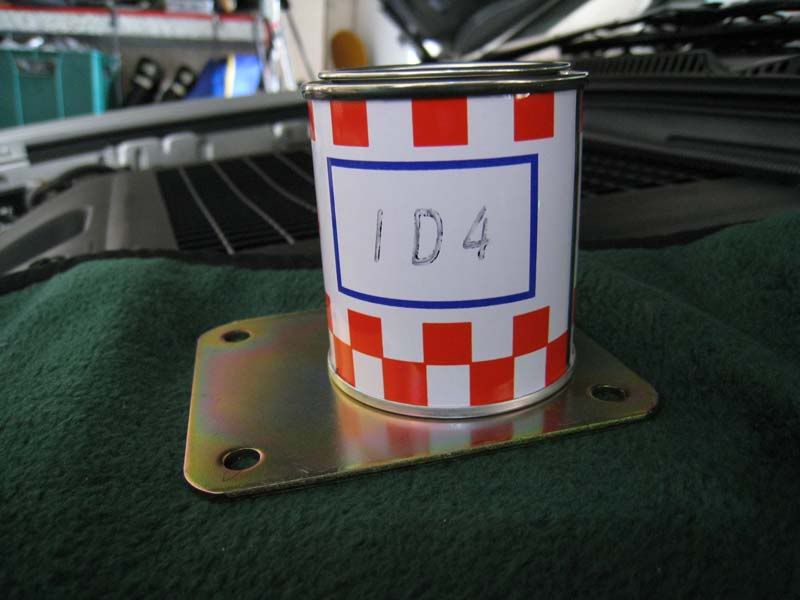
2.5 Protect the Bare Metal
Add some touchup paint to coat the bare-metal. Mine was supplied with the vehicle.
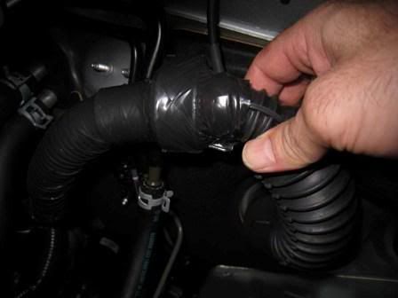
3 Running the Wire-Loom Through the Firewall
Whilst waiting for the paint to dry, now is the time to start running the wiring loom. With advice from Crammy and Plucker, I also ran mine through the firewall on the driver's side. This makes it easy to hook into power at the fuse-box. I also spent a lot of time poking the cables through the rubber-bung.
4 Location of Power Sources
You will need to locate two power sources, Illumination and Ignition/Accessory. A Voltmeter makes this straight-forward and is very handy for confirming your connections.
4.1 Illumination Power (Green Wire)
One source is for illuminating the switch when the headlights are on. You can access this from many places. Since the "Idle Start" button has an illumination source, I used that (Green wire). The switch is easily pushed out if you open the fuse box, reach up behind the switch and apply some pressure, perhaps with some wriggling (of the switch, that is!).
Notice that the ARB kit comes with a Scotch-Lock splicing connector (that's the bulky white object in the picture below). This made the splice a piece of cake!
4.2 Use Ignition or Accessory Power
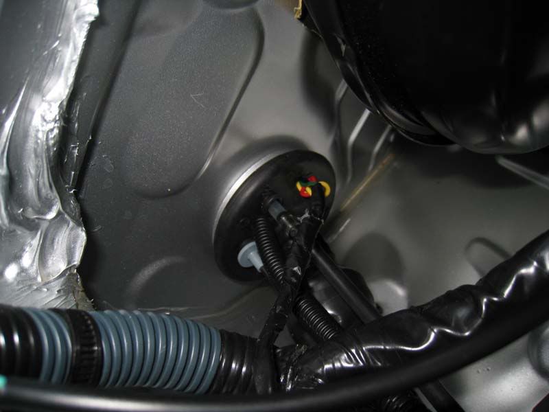
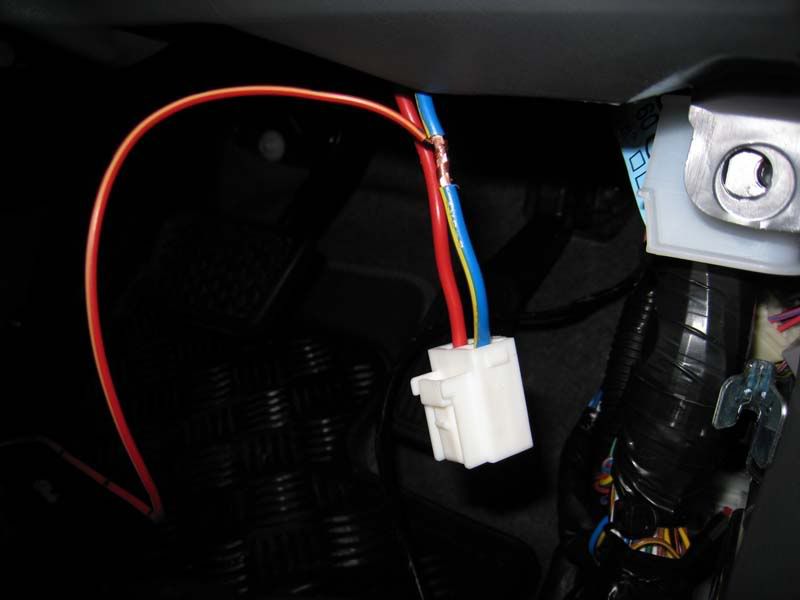
At this point, you might consider disconnecting the battery. I didn't, though after it was all done, other knowledgeable folk recommended taking this precaution. Note, that neither of the wires below are live as long as the key is in the OFF position, so I'm not sure what else is gained by disconnecting the battery.
The other power-source connects to the ignition or accessories power, (your choice), so only when you turn the key to the slected position will the compressor be operable. Fortunately, both power sources are readily accessible behind the fuse-box panel. Notice the thick guaged Blue/Yellow (Ignition) and Red (Accessories) wires.
Splice the ARB ignition wire onto the selected cable. Like others before me, I chose the Blue/Yellow (Ignition) cable. In the field, I found this to be a good choice as it encouraged me to keep the motor running whilst inflating the tyres; the turbo appreciates being run for a while after hard yards in the sand. Be sure to solder it or use automotive splicing connectors.
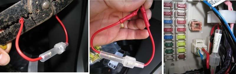
4.3 Fuse the Control Circuit
Notice the ARB wire is a smaller guage than the ignition/accessories wires. This suggests that an inline fuse will be required to protect the circuitry. (See Leachy's excellent posts on the next page for more details). Also, the ARB instructions mention the requirement to find a fused circuit:
Consequently, I installed a simple inline 10A fuse as the following pics show:
5 Fitting the ARB Switch
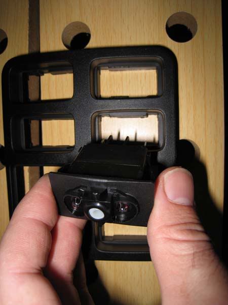
The ARB switch is wider than the slot in the Toyota face-plate, so some careful filing was needed. The faceplate is also easily removed by accessing the back of the face-plate from the fuse-box and apply pressure. It will pop out easily enough.
I used a metal file to slowly remove enough plastic so the switch squeezed in snugly. This was time-consuming!
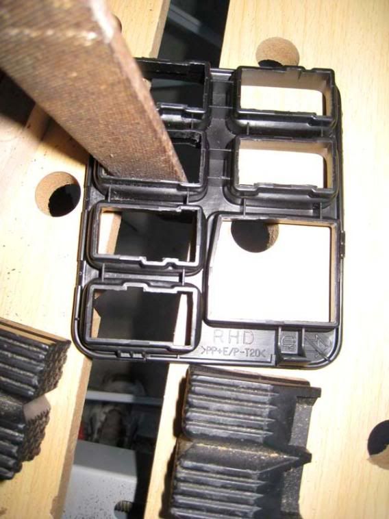
I found filing from the back-side of the plate was less-likely going to scratch the front-side. Be careful here!
I moved the standard Toyota switches to the top two slots. Unfortunately, the switch-blocks are keyed, so they only fit in one slot. I needed to rekey the top two slots with a cylinderical file to refit the Dimmer and Idle Start switches to the top two slots. The bottom 4 slots are now available for after-market switches.
The instructions are very clear about which wires to connect to the switch. After that, the face plate was refitted and lookin' good 8).
Time for lunch and a beer.
6 Bolting the Compressor
With the paint now dry, it was time to go back to bolting in the compressor. I decided to fit some high-density rubber foot-rests. My thinking was three-fold. Firstly, it reduces vibration stress on the thin-walled guard, secondly it isolates the heat from the body and paintwork and thirdly it provides a sound-cushion so sound-waves are not transmitted through the vehicle's body, turning it into one big subwoofer! The down-side is it reduces the penetration of each bolt, so it is much trickier to fit the backing-plate.
This was very time-consuming, but perserverence and redrilling one of the holes in the backing-plate eventually saw me through.
Nearly there! All that is needed now is to connect the wiring loom to the compressor and battery, as well as fitting the supplied T-connector and pressure switch, and don't forget the relay. This part is generic and well described in the instructions. Finish the job with split-cable-wrap and use cable-ties to secure the entire wiring loom.
Last but not least here is the end result. Also notice the yellow dust cap. I spent less then $5 on the dust-cap from Enzed. It is supposed to take high-temperatures, so we'll see how it goes.
7 Testing
Flick the switch and listen to the compressor vibrate into action. The pressure switch soon causes it to cut-out. At this point, you will know if you have an air-leak, since the compressor will startup automatically once again. If so, simply redo the threads, perhaps with extra plumbers tape.
Time to deflate and re-inflate your tyres!
7.1 Test Illumination of Switch
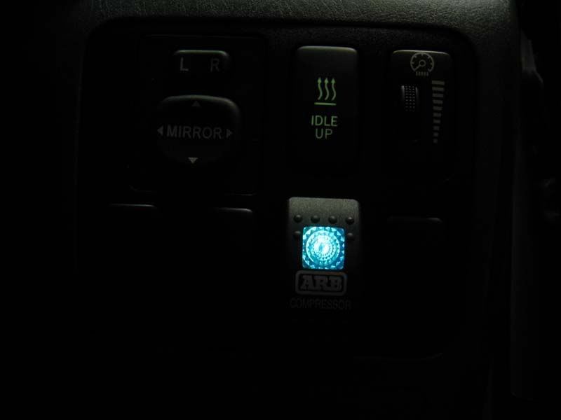
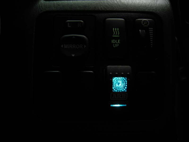
First a word on the ARB switch... The ARB toggle switch will clip on in either direction. The switch also has two lamps - one illuminates with the headlights and the other illuminates when the compressor is ON. Depending on which way you orient the switch, will determine which lamp is illuminated. The instructions had no helpful information here.
I initially set mine up so that the down-position turned the compressor ON. This also means that the large (less than subtle) lamp illuminates when the headlights are ON. I've since flipped the switch so now the small lamp is ON with the headlights. Of course, this also means the UP position is now ON. Oh well, not a big deal. You choose.
7.2 Inflation Test Results
My method was to inflate the first tyre from 14.5psi to 37.5psi and measure the time. This was my benchmark-time. I then inflated the remaining tyres for that benchmark-time and measured the pressure. If the pressure was still below 37.5psi, I measured the additional time it took to bring the tyre up to 37.5. Hope that makes sense. (Air temperature was 28C).
Very happy with that!
LFaR.
11-Mar-2008: Red wire is Accessories, Ignition is Blue/Yellow. Thanks to eagle-eyed Chuck.
12-Mar-2008: Final pic of installation.
14-Mar-2008: Brief description of removing switch and faceplate + precaution to disconnect battery + orientation of ARB toggle switch
06-Apr-2008: As per Leachy's post, make sure the control circuit is fused.
This is the definitive guide to installing the ARB High Output On-Board Air Compressor - CKMA12 in a 2008 Toyota Prado GXL D4D. Let me know if I've missed something - I'll keep updating this post as needed.
The topics covered include:
- The Product - ARB High Output On-Board Air Compressor - CKMA12[/*:m:3o8lo8md]
- Locating the Compressor[/*:m:3o8lo8md]
- Running the wire-loom through the firewall[/*:m:3o8lo8md]
- Location of Power Sources: Ignition or Accesories, and llumination[/*:m:3o8lo8md]
- Fitting the ARB Switch[/*:m:3o8lo8md]
- Bolting the Compressor[/*:m:3o8lo8md]
- Test Results[/*:m:3o8lo8md]
Whilst the instructions that are supplied with the compressor are first-rate, they are generic. This is intended to focus on the idiosyncrasies of the Prado installation. The install vehicle is a 2008 D4D GXL.
Related threads:
- Under Pressure - Blue Tongue IV or ARB CKMA12[/*:m:3o8lo8md]
- Under Bonnet Air Compressor[/*:m:3o8lo8md]
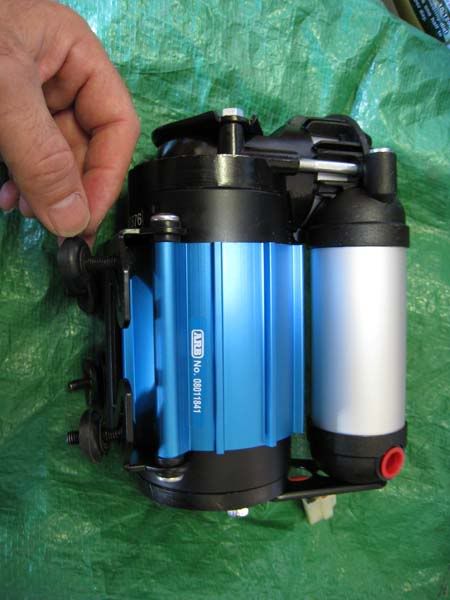
1. The Product
The price I paid was $280 for the compressor and $64 for the hose kit.
 [/*:m:3o8lo8md]
2. Locating the Compressor
Preferred location is the passenger-side, near the firewall and on the wheel arch.
 [/*:m:3o8lo8md]
2.1 Masking Tape
Lay some masking tape to protect the paint-work and also to assist later with drilling.
 [/*:m:3o8lo8md]
2.2 Orientation
This pump gets very hot, so mount it where there is no contact with other hoses and cables. For me, I preferred an orientation that kept it furthest from any hoses. This was a diagonal position, (North-East), though others have mounted theirs East-West or North-South. I will note that NE orientation meant that it was difficult to mount the backing-plate. Though, this seems to be a common problem with other orientations also. More on the backing plate later. Here is the orientation I chose:
 [/*:m:3o8lo8md]
Move any cables and hoses away from the work area. Be sure to remember to reattach them at the end of the job
 [/*:m:3o8lo8md]
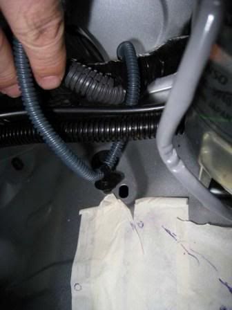 [/*:m:3o8lo8md]
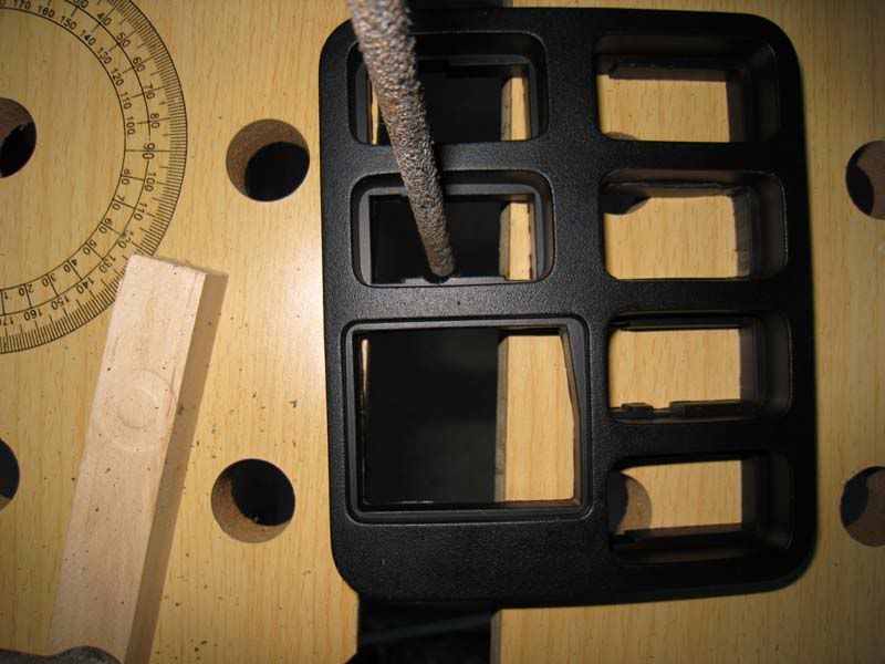
2.3 Say a Prayer and Start Drilling
Take a breath, double-check you have marked the drill-holes correctly and let the drilling begin. [I made a mistake at this step. I carefully laid the template at right-angles to the way it should have been. I ended up with 3 extra holes
:idea: I recommend you draw an arrow on the template to avoid my mistake.
:idea: Place a step by the car - it's easier to drill when standing on a 30cm platform
 [/*:m:3o8lo8md]
2.4 Clean Up as You Go
Vacuum up the metal shavings.
 [/*:m:3o8lo8md]
2.5 Protect the Bare Metal
Add some touchup paint to coat the bare-metal. Mine was supplied with the vehicle.
Artist at work![/*:m:3o8lo8md]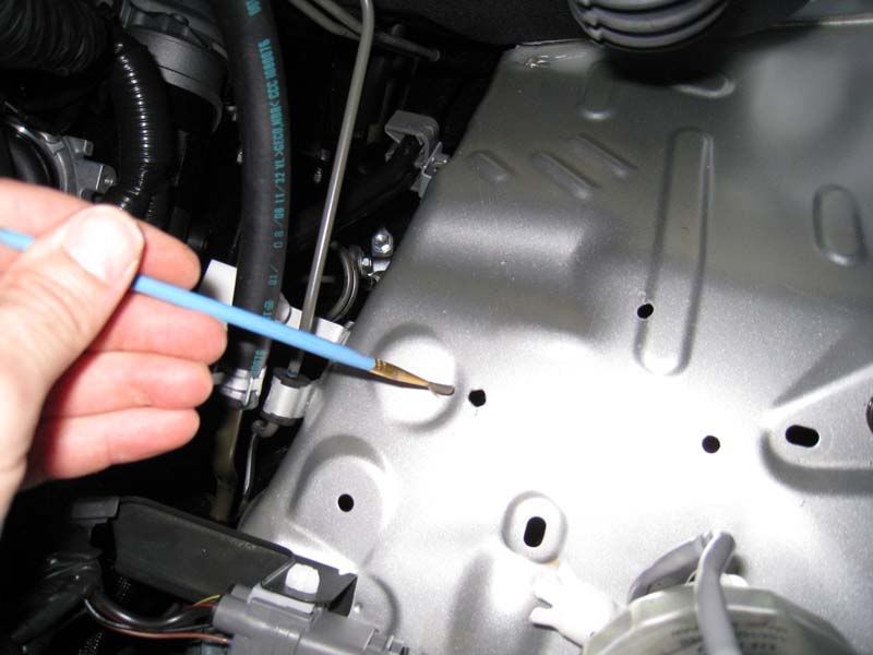 [/*:m:3o8lo8md]
3 Running the Wire-Loom Through the Firewall
Whilst waiting for the paint to dry, now is the time to start running the wiring loom. With advice from Crammy and Plucker, I also ran mine through the firewall on the driver's side. This makes it easy to hook into power at the fuse-box. I also spent a lot of time poking the cables through the rubber-bung.
- From the engine-bay, I used a sharp knife to open a slit, then started pushing the wiring loom through the rubber-bung.[/*:m:3o8lo8md]
 [/*:m:3o8lo8md]
- Then in the driver's footwell, I removed the kick-panel to access the rubber-bung from inside.[/*:m:3o8lo8md]
 [/*:m:3o8lo8md]
- Finally, another slit and carefully tugging the wiring loom through the firewall.[/*:m:3o8lo8md]
 [/*:m:3o8lo8md]
4 Location of Power Sources
You will need to locate two power sources, Illumination and Ignition/Accessory. A Voltmeter makes this straight-forward and is very handy for confirming your connections.
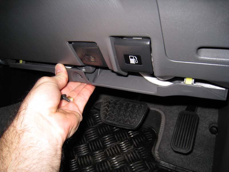
4.1 Illumination Power (Green Wire)
One source is for illuminating the switch when the headlights are on. You can access this from many places. Since the "Idle Start" button has an illumination source, I used that (Green wire). The switch is easily pushed out if you open the fuse box, reach up behind the switch and apply some pressure, perhaps with some wriggling (of the switch, that is!).
Notice that the ARB kit comes with a Scotch-Lock splicing connector (that's the bulky white object in the picture below). This made the splice a piece of cake!
 [/*:m:3o8lo8md]
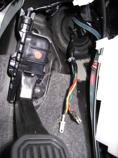
4.2 Use Ignition or Accessory Power
At this point, you might consider disconnecting the battery. I didn't, though after it was all done, other knowledgeable folk recommended taking this precaution. Note, that neither of the wires below are live as long as the key is in the OFF position, so I'm not sure what else is gained by disconnecting the battery.
The other power-source connects to the ignition or accessories power, (your choice), so only when you turn the key to the slected position will the compressor be operable. Fortunately, both power sources are readily accessible behind the fuse-box panel. Notice the thick guaged Blue/Yellow (Ignition) and Red (Accessories) wires.
 [/*:m:3o8lo8md]
Splice the ARB ignition wire onto the selected cable. Like others before me, I chose the Blue/Yellow (Ignition) cable. In the field, I found this to be a good choice as it encouraged me to keep the motor running whilst inflating the tyres; the turbo appreciates being run for a while after hard yards in the sand. Be sure to solder it or use automotive splicing connectors.
 [/*:m:3o8lo8md]
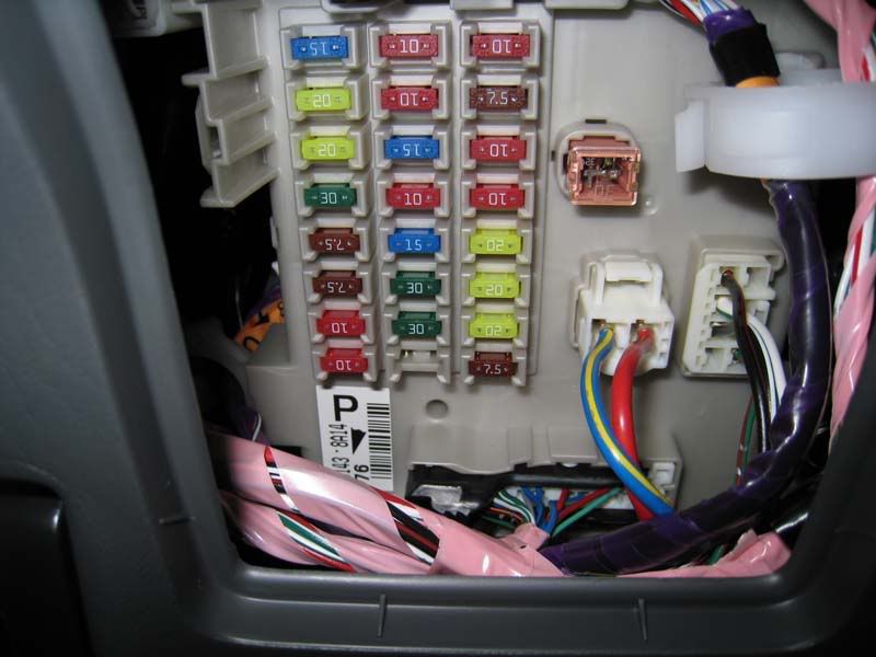
4.3 Fuse the Control Circuit
Notice the ARB wire is a smaller guage than the ignition/accessories wires. This suggests that an inline fuse will be required to protect the circuitry. (See Leachy's excellent posts on the next page for more details). Also, the ARB instructions mention the requirement to find a fused circuit:
Code:
NOTE: The desired outlet should supply positive 12V DC, be fused at a minimum of 8amps, and be live only when the vehicle ignition key is in either the "ACC" position or in the "ON" position.
5 Fitting the ARB Switch
The ARB switch is wider than the slot in the Toyota face-plate, so some careful filing was needed. The faceplate is also easily removed by accessing the back of the face-plate from the fuse-box and apply pressure. It will pop out easily enough.
I used a metal file to slowly remove enough plastic so the switch squeezed in snugly. This was time-consuming!
 .[/*:m:3o8lo8md]
I found filing from the back-side of the plate was less-likely going to scratch the front-side. Be careful here!
 [/*:m:3o8lo8md]
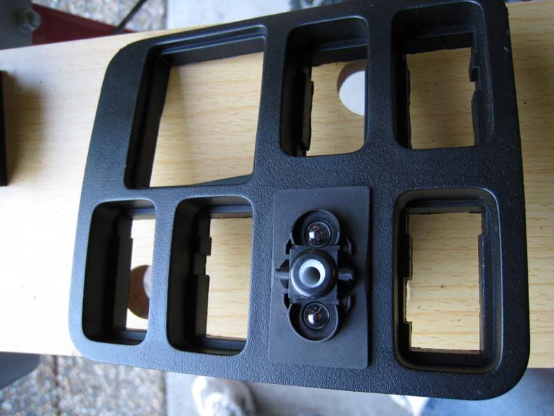 [/*:m:3o8lo8md]
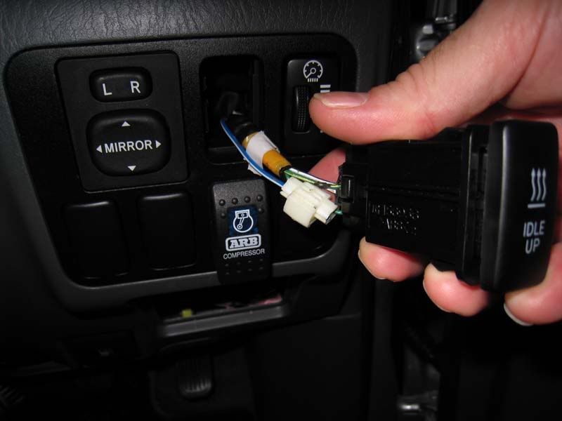
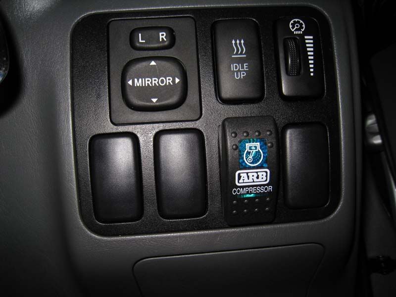
I moved the standard Toyota switches to the top two slots. Unfortunately, the switch-blocks are keyed, so they only fit in one slot. I needed to rekey the top two slots with a cylinderical file to refit the Dimmer and Idle Start switches to the top two slots. The bottom 4 slots are now available for after-market switches.
 [/*:m:3o8lo8md]
The instructions are very clear about which wires to connect to the switch. After that, the face plate was refitted and lookin' good 8).
 [/*:m:3o8lo8md]
Time for lunch and a beer.
6 Bolting the Compressor
With the paint now dry, it was time to go back to bolting in the compressor. I decided to fit some high-density rubber foot-rests. My thinking was three-fold. Firstly, it reduces vibration stress on the thin-walled guard, secondly it isolates the heat from the body and paintwork and thirdly it provides a sound-cushion so sound-waves are not transmitted through the vehicle's body, turning it into one big subwoofer! The down-side is it reduces the penetration of each bolt, so it is much trickier to fit the backing-plate.
 [/*:m:3o8lo8md]
This was very time-consuming, but perserverence and redrilling one of the holes in the backing-plate eventually saw me through.
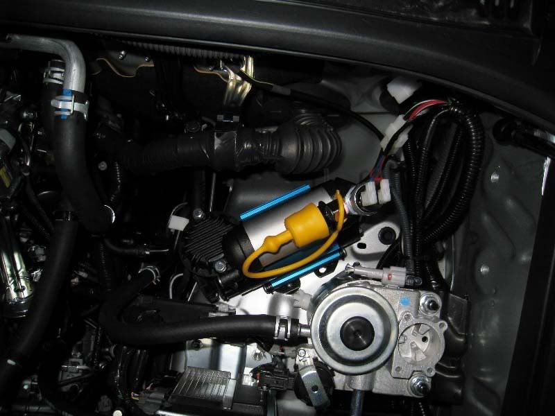
Nearly there! All that is needed now is to connect the wiring loom to the compressor and battery, as well as fitting the supplied T-connector and pressure switch, and don't forget the relay. This part is generic and well described in the instructions. Finish the job with split-cable-wrap and use cable-ties to secure the entire wiring loom.
Last but not least here is the end result. Also notice the yellow dust cap. I spent less then $5 on the dust-cap from Enzed. It is supposed to take high-temperatures, so we'll see how it goes.
 [/*:m:3o8lo8md]
7 Testing
Flick the switch and listen to the compressor vibrate into action. The pressure switch soon causes it to cut-out. At this point, you will know if you have an air-leak, since the compressor will startup automatically once again. If so, simply redo the threads, perhaps with extra plumbers tape.
Time to deflate and re-inflate your tyres!
7.1 Test Illumination of Switch
First a word on the ARB switch... The ARB toggle switch will clip on in either direction. The switch also has two lamps - one illuminates with the headlights and the other illuminates when the compressor is ON. Depending on which way you orient the switch, will determine which lamp is illuminated. The instructions had no helpful information here.
I initially set mine up so that the down-position turned the compressor ON. This also means that the large (less than subtle) lamp illuminates when the headlights are ON. I've since flipped the switch so now the small lamp is ON with the headlights. Of course, this also means the UP position is now ON. Oh well, not a big deal. You choose.
- Compressor on, headlights are off.[list:3o8lo8md]
 [/*:m:3o8lo8md]
 [/*:m:3o8lo8md]
 [/*:m:3o8lo8md]
7.2 Inflation Test Results
My method was to inflate the first tyre from 14.5psi to 37.5psi and measure the time. This was my benchmark-time. I then inflated the remaining tyres for that benchmark-time and measured the pressure. If the pressure was still below 37.5psi, I measured the additional time it took to bring the tyre up to 37.5. Hope that makes sense. (Air temperature was 28C).
- Tyre 1: 14.5 -> 37.5 : 1 min 55s (benchmark time) [/*:m:3o8lo8md]
- Tyre 2: 14.5 -> 37.5 : 1 min 55s [/*:m:3o8lo8md]
- Tyre 3: 14.5 -> 36.5 : 1 min 55s + 4 seconds for 36.5 -> 37.5 [/*:m:3o8lo8md]
- Tyre 4: 14.5 -> 36.5 : 1 min 55s + 4 seconds for 36.5 -> 37.5 [/*:m:3o8lo8md]
- Spare : 14.5 -> 37.5 : 1 min 55s[/*:m:3o8lo8md]
Very happy with that!
LFaR.
Comment