 Tweet
Tweet
Re: Install of ARB On-Board Air Compressor CKMA12
We probably didn't need yet another install "how to" for the ARB compressor as LFAR has already done an extremely good job with his detailed pics and write up. Subsequent replies have also pretty much said all that needs to be said. The more I went with this though the more it ended up as a write up anyhow. Someone might find it useful.
************************************************** ***
I've been threatening to do this for some time now. As I'm a little sick of dragging a portable air compressor out of a tightly packed load space while on a trip. There's nothing at all wrong with portable air compressors. However, I had some spare space under the bonnet and thought I could fit a compressor under there and free up a little load space inside the car, added to this, all I have to do now is retrieve the air hose from it's storage place under the seat, connect it up and I'm ready to go.
With a view to possible future Air Lockers, I chose ARB's "High Output On-Board Air Supply" or model CKMA12 compressor. This seems like a solid enough unit and from reading through the forum I know that other members have them fitted. As the CKMA12 is primarily used for Air Locker installations, it does not come with an air hose and fittings for inflating tyres. ARB sell the "Air Compressor Hose Kit" that goes with the CKMA12 which includes orange high temp air hose plus fittings for tyre valves etc.

As of 22/08/09 ARB's (Perth) prices were $304.50 for the compressor and $57.95 for the Air Compressor Hose kit.
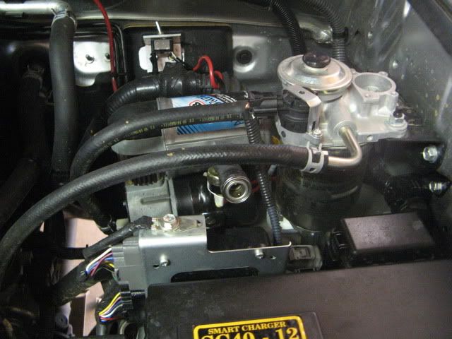
Here's the unit in close up. The compressor comes with a pressure switch, which you can see in the top left of the pic below with the electrical connectors coming out. The way it works is, when you flick the switch in the cab, the compressor will run for a few seconds until the air pressure builds up to 100 PSI. Then the pressure switch will turn the compressor off. You then attach your air hose to your deflated tyre and begin to inflate it, when the air pressure in the system drops to 70psi, the pressure switch will turn the compressor on again to maintain pressure while you're blowing your tyre up. This way, you don't have a constantly running compressor to worry about and can do your air stuff at your leisure. The other fitting close to the pressure switch is where you connect your air hoses etc for inflating tyres. You'll also see two smallish black grub screws in in the side of the silver cylinder on top. That is where you'd be attaching the solenoids for your air lockers if you had them fitted, so it's a good idea to try and leave a little space in that area once installed so you've got room for the solenoids later, if you're planning to go that route like I am.

The CKMA12 comes with it's own wiring harness, which is complete and will not require any extra wiring to be supplied by you, unless you find you need to extend any of the power leads to reach into spots further away than ARB has anticipated. Upon first inspection, the wiring harness appears somewhat complex. Don't worry about that though as a full wiring diagram is provided in the installation instructions supplied with the unit. All the wires are colour coded so it's easy tell which wires go where, and once you know that, the remainder of the installation isn't exactly rocket science. ARB has split the wiring harness as below. The reason they do that is so you can easily thread the thin connectors through the firewall, one at a time if necessary. Once threaded through the firewall you can connect the individual wires into the plastic plug provided, this then allows you to plug in the "inside" wiring section as shown below.

So here's where the compressor is going in my rig, front drivers side just behind the headlight, which is the space set aside for the 2nd battery in most situations. In my case however, ARB in their infinite wisdom fitted my 2nd battery on the passenger side at the rear of the engine bay. Only an N50 battery though.

See the fairly large rubber grommet in the pic below, find the bottom of the gas strut and look down below it. It's there hidden behind the large cable sheaths. That's where you'll need to run the wiring from the compressor through into the cab. Not the best pic I know but hey, it's the effort that counts right :roll: ? You need to cut a small slit in the rubber grommet so you can feed the wiring through, no need to hack too large a hole, as small as you can get away with to allow it to seal as much as possible after the wires are fed through.

Here's the little buggers! Ready to go through.

And a close up! Complete with wiring harness fed through. Lit by my LED Lenser. 8)

And here's the wiring coming through into the drivers footwell. It's a bit tight in there, but if you get your head right down next to the pedals you can look up and see the rubber grommet from the inside. I had a pair of pointy nose pliers to help me grab the plug ends as they appeared through the grommet. Patience is the key here, as it's very fiddly and tight up in there. I did one wire at a time and then pulled the entire cable through once all individual wires had been threaded through.

Right! The cable is through! Now connect the individual wires into the provided plastic plug, making sure you get the coloured wires into the same positions as they are on the piece of wiring harness you're going to be plugging into. Then, plug in, and you're ready to start pulling your dash apart. 8)

That's the spot I'm going to install the compressor switch just in one of those blanks below the ignition. The switch is included with the compressor by the way, no need to go out and buy one..... unless you want something funky.... :roll:

That accessory switch panel can actually be popped out. Remove the access door for the fuse array below it, and also remove some of the switch blanks so you can get your fingers in behind there. Feel up behind the switch panel with your fingers and you'll be able to push the blanks out from behind, they have very simple catches you can press in and presto! Out they'll come 8) ! The switch panel is another story, basically, it also has catches on each side that clip it in. Start with the bottom and firmly push the edges on either side from behind, you should also be able to feel for the catches that secure it, although they aren't as pronounced as the ones that secure the blanks. You'll need a firm push to get it started. Once the bottom has popped out you can gently unclip the remaining edges.

And out it comes.

The switches that are already in the switch panel can also be unplugged and popped out without any issue at all. The reason I've pulled the face plate out like that is because I had to do a little filing and cutting in the position I chose so the ARB switch would fit. Not too much of a drama, just cut and file a little bit at a time until the ARB switch goes in there nice and firmly.
You need to connect two further wires to the switch in addition to the ones coming through from the engine bay. (1) A power source that becomes active with the ignition switch. (2) A power source that becomes active with the park lights. Obviously, the park lights wire is simply to turn a light on in the switch at night when you've got your headlights on, and so isn't strictly necessary if you don't feel like it. The ignition power switch IS necessary though. The Idea is that you will only be able to activate the compressor if you've turned the key to the accessory position, or if you've got the engine running. It won't come on strangely by itself in the dead of night (hopefully) this way. So you'll need to turn the key and then hit the switch to activate.
I found a spare plug tied back in behind there that I was able to connect the switch light to, you can see it there in the pic below. Seems that all such lighting wires were dark green in my case. Basically, the multimeter is your friend here. Turn on the park lights and see which wires or contacts are active in and around the fuse box area. Switch off the park lights to double check the contact is indeed dead with the lights off. Repeat this procedure for the ignition power. I found a fat white cable to the far right of the fuse box area which became active in the accessory key position.

And there is the finished product. Your in-cab work is now done and dusted.

Moving back to the engine bay now. I needed to find somewhere to run the power cables across the front of the vehicle. Fortunately, another power cable already does exactly that and all you need to do is follow the same route. Use the most important tool anyone should ever own (a pocket knife 8) ) to prise up the clips that hold the plastic panel down at the front of the engine bay. The bottle opener / screwdriver thingy seemed best for the job.

And off it comes to reveal the cross member underneath. A fairly thick, sheathed cable runs underneath / inside that crossmember and all you need do is tie the compressor cable to it with cable ties. There's also some other holes along the way you can use as tie down points too if you feel like it.

You need to be a little careful to route the cable through as straight as possible as ARB has only given you just enough to make it across the front of the Prado. You can see I've had to route the cable over the top of the battery holder in order to have enough cable free to reach the battery terminals. Interestingly, the wiring pops into the battery holder crosspiece quite nicely for a bit more of a Pro look. The black wire I've routed over to an earthing point that is attached to the side of the engine bay. The earth was there from new so I'd assume other D4D's would be the same.

So at this stage I was getting pretty close to a complete install. I sat the compressor in the space and connected it up to give it a test before drilling the mounting holes and making it a permanent fixture. Note the orange 40 amp fuse between the wiper reservoir filler and the radiator at the very bottom of the picture. It's a good idea to have the fuse in an accessible location in case it does blow. You really don't want to be bollocksing about in a fiddly location trying to access the fuse holder in the middle of the Lancelin dunes. The wiring harness is fused between the battery and the compressor. Both fuse and attached housing come with the the wiring harness. Please read Leachy_9's reasons for adding in an additional fuse at the switch end of the wiring harness in the cab. I'll include Leachy_9's explanations for this at the end of the write up as he raises a very good point. With the test completed, it's time to bolt that sucker down!

I took the more expensive route here of purchasing an Outback battery tray designed specifically for bolting into a Diesel 120 Series Prado. Outback also make one for the petrol V6 Prado's which are almost identical except for a few small changes. ARB sell these for $148.64 as of 12/09/09. They are very solid bits of gear and are designed to fit an N70 sized battery, so you get plenty of room if you're using it as an accessory space. They are solid steel and look like they'll cop a beating. Why did I go this way? Main reason being I did not want to drill holes through the wheel arch. The Outback tray uses two existing threaded mounting holes in this space to bolt down the bottom of the tray. You do however need to drill two 8mm holes into the side of the engine bay so you can bolt down the side of the battery tray there. The tray will also provide extra mounting space that I won't mind drilling for other accessories in the future.

Here I've drilled the holes. Bolt down the tray in position with the bolts in the bottom of the tray, and then mark the side hole positions. Take the tray out and load up the drill with a smaller drill bit first to get a pilot hole made. The sheet metal you're drilling through is surprisingly thin so if you go in with the full 8mm bit to begin with you can end up with a fairly messy job. Once you've got the 8mm holes drilled then it's a good idea to throw on some paint to protect the bare steel you've uncovered. I have a silver spray can that is touch dry in 10 minutes.

Before I could bolt the tray in though, I needed to bolt in the compressor itself. So I used the compressor's mounting plate as a template to mark out the drill holes in the battery tray.

Once again I gave the drill holes a spray with silver paint to cover any bare metal.

The Outback tray comes with a bracket containing two bolts that you push through the two holes you drilled, from the inside. In order to get in there you need to remove a portion of the plastic splash guard in the wheel arch as below. I went right to the very bottom of the splash guard and removed the two screws at bumper level to give me a bit more play in the guard to remove it. You only need enough room to get your hand up in there, so it isn't necessary to remove the whole thing. See below.

So here I'm pretty much done. I've bolted in the Outback battery tray (4 bolts in total) and bolted the compressor into the tray itself. You can see I've put it right over to the side to leave as much free space in the battery tray as possible.


All Done!! I've covered any loose wiring with protective sheath and connected up the orange air hose for the grand test. 8) All ran smoothly 8) 8) . No solid figures yet but I'd estimate I pumped the spare from 18PSI to 40PSI in around a minute. The Staun's came in very handy for this testing I might add.

The only thing left to say is about the extra fuse on the cab switch side of the wiring harness. For completeness, I've included Leachy_9's comments about fusing the switch side of the wiring harness.
We probably didn't need yet another install "how to" for the ARB compressor as LFAR has already done an extremely good job with his detailed pics and write up. Subsequent replies have also pretty much said all that needs to be said. The more I went with this though the more it ended up as a write up anyhow. Someone might find it useful.
************************************************** ***
I've been threatening to do this for some time now. As I'm a little sick of dragging a portable air compressor out of a tightly packed load space while on a trip. There's nothing at all wrong with portable air compressors. However, I had some spare space under the bonnet and thought I could fit a compressor under there and free up a little load space inside the car, added to this, all I have to do now is retrieve the air hose from it's storage place under the seat, connect it up and I'm ready to go.
With a view to possible future Air Lockers, I chose ARB's "High Output On-Board Air Supply" or model CKMA12 compressor. This seems like a solid enough unit and from reading through the forum I know that other members have them fitted. As the CKMA12 is primarily used for Air Locker installations, it does not come with an air hose and fittings for inflating tyres. ARB sell the "Air Compressor Hose Kit" that goes with the CKMA12 which includes orange high temp air hose plus fittings for tyre valves etc.
As of 22/08/09 ARB's (Perth) prices were $304.50 for the compressor and $57.95 for the Air Compressor Hose kit.
Here's the unit in close up. The compressor comes with a pressure switch, which you can see in the top left of the pic below with the electrical connectors coming out. The way it works is, when you flick the switch in the cab, the compressor will run for a few seconds until the air pressure builds up to 100 PSI. Then the pressure switch will turn the compressor off. You then attach your air hose to your deflated tyre and begin to inflate it, when the air pressure in the system drops to 70psi, the pressure switch will turn the compressor on again to maintain pressure while you're blowing your tyre up. This way, you don't have a constantly running compressor to worry about and can do your air stuff at your leisure. The other fitting close to the pressure switch is where you connect your air hoses etc for inflating tyres. You'll also see two smallish black grub screws in in the side of the silver cylinder on top. That is where you'd be attaching the solenoids for your air lockers if you had them fitted, so it's a good idea to try and leave a little space in that area once installed so you've got room for the solenoids later, if you're planning to go that route like I am.
The CKMA12 comes with it's own wiring harness, which is complete and will not require any extra wiring to be supplied by you, unless you find you need to extend any of the power leads to reach into spots further away than ARB has anticipated. Upon first inspection, the wiring harness appears somewhat complex. Don't worry about that though as a full wiring diagram is provided in the installation instructions supplied with the unit. All the wires are colour coded so it's easy tell which wires go where, and once you know that, the remainder of the installation isn't exactly rocket science. ARB has split the wiring harness as below. The reason they do that is so you can easily thread the thin connectors through the firewall, one at a time if necessary. Once threaded through the firewall you can connect the individual wires into the plastic plug provided, this then allows you to plug in the "inside" wiring section as shown below.
So here's where the compressor is going in my rig, front drivers side just behind the headlight, which is the space set aside for the 2nd battery in most situations. In my case however, ARB in their infinite wisdom fitted my 2nd battery on the passenger side at the rear of the engine bay. Only an N50 battery though.
See the fairly large rubber grommet in the pic below, find the bottom of the gas strut and look down below it. It's there hidden behind the large cable sheaths. That's where you'll need to run the wiring from the compressor through into the cab. Not the best pic I know but hey, it's the effort that counts right :roll: ? You need to cut a small slit in the rubber grommet so you can feed the wiring through, no need to hack too large a hole, as small as you can get away with to allow it to seal as much as possible after the wires are fed through.
Here's the little buggers! Ready to go through.
And a close up! Complete with wiring harness fed through. Lit by my LED Lenser. 8)
And here's the wiring coming through into the drivers footwell. It's a bit tight in there, but if you get your head right down next to the pedals you can look up and see the rubber grommet from the inside. I had a pair of pointy nose pliers to help me grab the plug ends as they appeared through the grommet. Patience is the key here, as it's very fiddly and tight up in there. I did one wire at a time and then pulled the entire cable through once all individual wires had been threaded through.
Right! The cable is through! Now connect the individual wires into the provided plastic plug, making sure you get the coloured wires into the same positions as they are on the piece of wiring harness you're going to be plugging into. Then, plug in, and you're ready to start pulling your dash apart. 8)
That's the spot I'm going to install the compressor switch just in one of those blanks below the ignition. The switch is included with the compressor by the way, no need to go out and buy one..... unless you want something funky.... :roll:
That accessory switch panel can actually be popped out. Remove the access door for the fuse array below it, and also remove some of the switch blanks so you can get your fingers in behind there. Feel up behind the switch panel with your fingers and you'll be able to push the blanks out from behind, they have very simple catches you can press in and presto! Out they'll come 8) ! The switch panel is another story, basically, it also has catches on each side that clip it in. Start with the bottom and firmly push the edges on either side from behind, you should also be able to feel for the catches that secure it, although they aren't as pronounced as the ones that secure the blanks. You'll need a firm push to get it started. Once the bottom has popped out you can gently unclip the remaining edges.
And out it comes.
The switches that are already in the switch panel can also be unplugged and popped out without any issue at all. The reason I've pulled the face plate out like that is because I had to do a little filing and cutting in the position I chose so the ARB switch would fit. Not too much of a drama, just cut and file a little bit at a time until the ARB switch goes in there nice and firmly.
You need to connect two further wires to the switch in addition to the ones coming through from the engine bay. (1) A power source that becomes active with the ignition switch. (2) A power source that becomes active with the park lights. Obviously, the park lights wire is simply to turn a light on in the switch at night when you've got your headlights on, and so isn't strictly necessary if you don't feel like it. The ignition power switch IS necessary though. The Idea is that you will only be able to activate the compressor if you've turned the key to the accessory position, or if you've got the engine running. It won't come on strangely by itself in the dead of night (hopefully) this way. So you'll need to turn the key and then hit the switch to activate.
I found a spare plug tied back in behind there that I was able to connect the switch light to, you can see it there in the pic below. Seems that all such lighting wires were dark green in my case. Basically, the multimeter is your friend here. Turn on the park lights and see which wires or contacts are active in and around the fuse box area. Switch off the park lights to double check the contact is indeed dead with the lights off. Repeat this procedure for the ignition power. I found a fat white cable to the far right of the fuse box area which became active in the accessory key position.
And there is the finished product. Your in-cab work is now done and dusted.
Moving back to the engine bay now. I needed to find somewhere to run the power cables across the front of the vehicle. Fortunately, another power cable already does exactly that and all you need to do is follow the same route. Use the most important tool anyone should ever own (a pocket knife 8) ) to prise up the clips that hold the plastic panel down at the front of the engine bay. The bottle opener / screwdriver thingy seemed best for the job.
And off it comes to reveal the cross member underneath. A fairly thick, sheathed cable runs underneath / inside that crossmember and all you need do is tie the compressor cable to it with cable ties. There's also some other holes along the way you can use as tie down points too if you feel like it.
You need to be a little careful to route the cable through as straight as possible as ARB has only given you just enough to make it across the front of the Prado. You can see I've had to route the cable over the top of the battery holder in order to have enough cable free to reach the battery terminals. Interestingly, the wiring pops into the battery holder crosspiece quite nicely for a bit more of a Pro look. The black wire I've routed over to an earthing point that is attached to the side of the engine bay. The earth was there from new so I'd assume other D4D's would be the same.
So at this stage I was getting pretty close to a complete install. I sat the compressor in the space and connected it up to give it a test before drilling the mounting holes and making it a permanent fixture. Note the orange 40 amp fuse between the wiper reservoir filler and the radiator at the very bottom of the picture. It's a good idea to have the fuse in an accessible location in case it does blow. You really don't want to be bollocksing about in a fiddly location trying to access the fuse holder in the middle of the Lancelin dunes. The wiring harness is fused between the battery and the compressor. Both fuse and attached housing come with the the wiring harness. Please read Leachy_9's reasons for adding in an additional fuse at the switch end of the wiring harness in the cab. I'll include Leachy_9's explanations for this at the end of the write up as he raises a very good point. With the test completed, it's time to bolt that sucker down!
I took the more expensive route here of purchasing an Outback battery tray designed specifically for bolting into a Diesel 120 Series Prado. Outback also make one for the petrol V6 Prado's which are almost identical except for a few small changes. ARB sell these for $148.64 as of 12/09/09. They are very solid bits of gear and are designed to fit an N70 sized battery, so you get plenty of room if you're using it as an accessory space. They are solid steel and look like they'll cop a beating. Why did I go this way? Main reason being I did not want to drill holes through the wheel arch. The Outback tray uses two existing threaded mounting holes in this space to bolt down the bottom of the tray. You do however need to drill two 8mm holes into the side of the engine bay so you can bolt down the side of the battery tray there. The tray will also provide extra mounting space that I won't mind drilling for other accessories in the future.
Here I've drilled the holes. Bolt down the tray in position with the bolts in the bottom of the tray, and then mark the side hole positions. Take the tray out and load up the drill with a smaller drill bit first to get a pilot hole made. The sheet metal you're drilling through is surprisingly thin so if you go in with the full 8mm bit to begin with you can end up with a fairly messy job. Once you've got the 8mm holes drilled then it's a good idea to throw on some paint to protect the bare steel you've uncovered. I have a silver spray can that is touch dry in 10 minutes.
Before I could bolt the tray in though, I needed to bolt in the compressor itself. So I used the compressor's mounting plate as a template to mark out the drill holes in the battery tray.
Once again I gave the drill holes a spray with silver paint to cover any bare metal.
The Outback tray comes with a bracket containing two bolts that you push through the two holes you drilled, from the inside. In order to get in there you need to remove a portion of the plastic splash guard in the wheel arch as below. I went right to the very bottom of the splash guard and removed the two screws at bumper level to give me a bit more play in the guard to remove it. You only need enough room to get your hand up in there, so it isn't necessary to remove the whole thing. See below.
So here I'm pretty much done. I've bolted in the Outback battery tray (4 bolts in total) and bolted the compressor into the tray itself. You can see I've put it right over to the side to leave as much free space in the battery tray as possible.
All Done!! I've covered any loose wiring with protective sheath and connected up the orange air hose for the grand test. 8) All ran smoothly 8) 8) . No solid figures yet but I'd estimate I pumped the spare from 18PSI to 40PSI in around a minute. The Staun's came in very handy for this testing I might add.
The only thing left to say is about the extra fuse on the cab switch side of the wiring harness. For completeness, I've included Leachy_9's comments about fusing the switch side of the wiring harness.
Originally posted by Leachy_9


Comment