 Tweet
Tweet
Hi all,
Hope this is the right place for this ...
I decided to put in a 40mm body lift on the 120 this last weekend. What a palaver 8O
The chassis diagram shows this:

and we can get, in the UK, a fabricated kit of spacers milled from billet aluminium and complete with bolts and 'instructions'. So you�d think this was all relatively straightforward, especially with the instructions, which essentially say:
1. Undo body mount bolts
2. Slacken off the steering rod joints
3. Stretch out the brake line coil from the master cylinder
4. Use a 2-arm lift to lift the body up and remove the mount bolts
5. Insert the spacers on top of or in-between the OEM cushions
6. Replace the bolts with the new ones supplied
7. Lower the body
8. Tighten up the new nuts
9. Tighten up the steering shaft joints
What it DOESN�T say, is that the steering spacer supplied has to be fitted in-between the existing rag-joint, and that the radiator and front bumper have to be re-mounted. Also, the OEM skirt that seals the intercooler to the bonnet will now be too short, as will be the transfer lever �
It does say that there will be a gap between the bumper and the body. Well, that�s fine if the bumper isn�t actually mounted to the body � the 120 bumper is! As is the rear bumper. :evil:
So � what started out as a relatively painless bit of work for 2 of us last Saturday turned into a marathon effort involving welders, new custom bolts, custom spacers, custom drop plates �. and a mad dash to beat a train I had to catch 8O
The two bolts through the front mounts are the right length as supplied. EVERY other bolt was wrong, either too long (for the bump-stop mounts and the steering spacer) or too short (every other chassis mount point!)
Additionally, the steering spacer centre hole was too small � it had to be re-drilled to 10mm, and the spacer is too thick � it needed to be about � of what it was supplied as. Also, the two holes for the original bolts to fit into were too short!!
So basically, the kit, as supplied, was crap.
On top of it all, it rained torrentially, so we had to rig a huge tarp over the work area, and tie it off to whatever we could find � and another two down as ground sheets.
So the real instruction sheet should look like this (a bit):
1. Undo body mount bolts
2. Slacken off the steering rod rag joint
3. Stretch out the brake line coil from the master cylinder
3. Remove the front bumper, second battery (for Euro vehicles) and drop the washer water bottle to gain access to the front chassis mounts
4. Undo the rear bumper lower retaining screws so it can move
5. Remove the under-slung spare tyre
6. Bash flat the support / guide loop attached to the body, or else you�ll never get the spare wheel winch rod back into the winch to wind the spare back up!
6. Use a 2-arm lift to lift the body up and remove the mount bolts
7. Insert the spacers on top of or in-between the OEM cushions
8. Replace the bolts with the new ones supplied, after making sure that the bump-stop ones are the right length, as are the side and rear bolts
9. Lower the body
10. Tighten up the new nuts
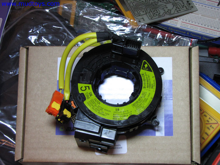
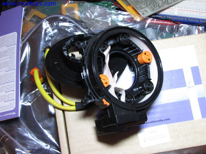
11. Insert the steering spacer in the rag joint (under the steering column inside the vehicle � you need to be a pygmy contortionist to get there. BIG WARNING�. DO NOT spin the steering wheel while doing this � we did, and destroyed the spiral Switch in the horn cover � Mr T wants �200 for a new one. So now I have no hooter, no air-bag and no cruiser control!
11. Tighten up the steering shaft joints
12. Disconnect the other battery for 30 minutes so the VSC / ABS / Yaw sensors get re-set, because otherwise things will be out-of-kilter when you try and drive
13. While doing this, make and fit the radiator drop plates, so that the engine fan does not foul on the one-piece cowl (at the bottom)
14. Make two extension plates to lift the front bumper-bar mounts by 40 mm so that the front bumper cover can be re-fitted. One of the two studs will need to be taken out so it all fits together again properly� I think this may be worse if you have an ARB or similar bull-bar, and may require a bit more planning and thought.
Once you�re happy it�s all done, and you�ve got a funny-looking rear bumper, go for a drive. That�s when we discovered the yaw sensor was playing up (related to turning the steering and breaking the Spiral Switch). I could get to 20kph in a straight line before the brakes locked and I had to stop � the ECU thought I was accelerating too fast into a tight corner � the wheels were straight but the steering wheel thought it was in a hard lock!
Anyway, it�s done � a new Spiral Switch is on it�s way from flea-bay, and that will fix the last electronic niggle. I still need to decide what to do about the rear bumper cover � I feel a custom build coming on �
Some photos were taken, but as the problem list grew longer, time grew shorter, and the camera was left alone. I�ll post what I have later. The final result is this:
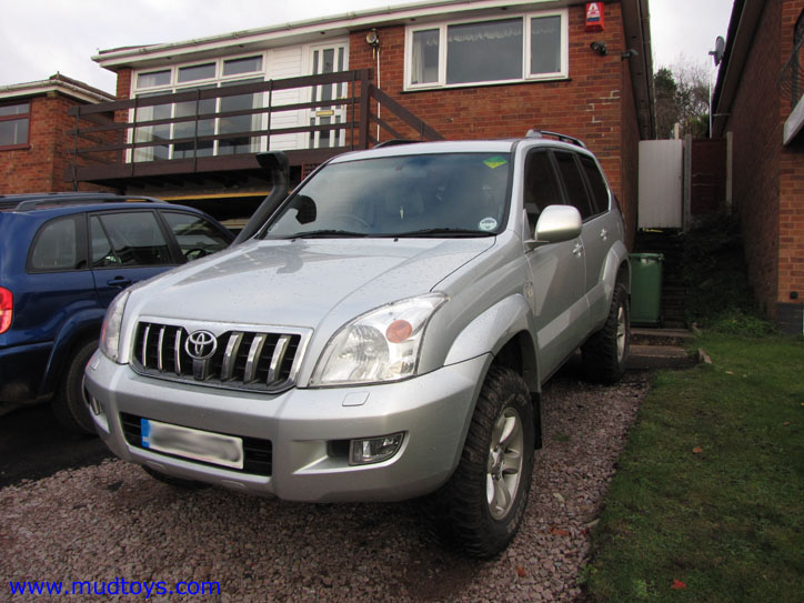
Thanks to Chris Jerman, without whose skills and abilities this would still be in bits in a driveway :lol:
Hope this is the right place for this ...
I decided to put in a 40mm body lift on the 120 this last weekend. What a palaver 8O
The chassis diagram shows this:
and we can get, in the UK, a fabricated kit of spacers milled from billet aluminium and complete with bolts and 'instructions'. So you�d think this was all relatively straightforward, especially with the instructions, which essentially say:
1. Undo body mount bolts
2. Slacken off the steering rod joints
3. Stretch out the brake line coil from the master cylinder
4. Use a 2-arm lift to lift the body up and remove the mount bolts
5. Insert the spacers on top of or in-between the OEM cushions
6. Replace the bolts with the new ones supplied
7. Lower the body
8. Tighten up the new nuts
9. Tighten up the steering shaft joints
What it DOESN�T say, is that the steering spacer supplied has to be fitted in-between the existing rag-joint, and that the radiator and front bumper have to be re-mounted. Also, the OEM skirt that seals the intercooler to the bonnet will now be too short, as will be the transfer lever �
It does say that there will be a gap between the bumper and the body. Well, that�s fine if the bumper isn�t actually mounted to the body � the 120 bumper is! As is the rear bumper. :evil:
So � what started out as a relatively painless bit of work for 2 of us last Saturday turned into a marathon effort involving welders, new custom bolts, custom spacers, custom drop plates �. and a mad dash to beat a train I had to catch 8O
The two bolts through the front mounts are the right length as supplied. EVERY other bolt was wrong, either too long (for the bump-stop mounts and the steering spacer) or too short (every other chassis mount point!)
Additionally, the steering spacer centre hole was too small � it had to be re-drilled to 10mm, and the spacer is too thick � it needed to be about � of what it was supplied as. Also, the two holes for the original bolts to fit into were too short!!
So basically, the kit, as supplied, was crap.
On top of it all, it rained torrentially, so we had to rig a huge tarp over the work area, and tie it off to whatever we could find � and another two down as ground sheets.
So the real instruction sheet should look like this (a bit):
1. Undo body mount bolts
2. Slacken off the steering rod rag joint
3. Stretch out the brake line coil from the master cylinder
3. Remove the front bumper, second battery (for Euro vehicles) and drop the washer water bottle to gain access to the front chassis mounts
4. Undo the rear bumper lower retaining screws so it can move
5. Remove the under-slung spare tyre
6. Bash flat the support / guide loop attached to the body, or else you�ll never get the spare wheel winch rod back into the winch to wind the spare back up!
6. Use a 2-arm lift to lift the body up and remove the mount bolts
7. Insert the spacers on top of or in-between the OEM cushions
8. Replace the bolts with the new ones supplied, after making sure that the bump-stop ones are the right length, as are the side and rear bolts
9. Lower the body
10. Tighten up the new nuts
11. Insert the steering spacer in the rag joint (under the steering column inside the vehicle � you need to be a pygmy contortionist to get there. BIG WARNING�. DO NOT spin the steering wheel while doing this � we did, and destroyed the spiral Switch in the horn cover � Mr T wants �200 for a new one. So now I have no hooter, no air-bag and no cruiser control!
11. Tighten up the steering shaft joints
12. Disconnect the other battery for 30 minutes so the VSC / ABS / Yaw sensors get re-set, because otherwise things will be out-of-kilter when you try and drive
13. While doing this, make and fit the radiator drop plates, so that the engine fan does not foul on the one-piece cowl (at the bottom)
14. Make two extension plates to lift the front bumper-bar mounts by 40 mm so that the front bumper cover can be re-fitted. One of the two studs will need to be taken out so it all fits together again properly� I think this may be worse if you have an ARB or similar bull-bar, and may require a bit more planning and thought.
Once you�re happy it�s all done, and you�ve got a funny-looking rear bumper, go for a drive. That�s when we discovered the yaw sensor was playing up (related to turning the steering and breaking the Spiral Switch). I could get to 20kph in a straight line before the brakes locked and I had to stop � the ECU thought I was accelerating too fast into a tight corner � the wheels were straight but the steering wheel thought it was in a hard lock!
Anyway, it�s done � a new Spiral Switch is on it�s way from flea-bay, and that will fix the last electronic niggle. I still need to decide what to do about the rear bumper cover � I feel a custom build coming on �
Some photos were taken, but as the problem list grew longer, time grew shorter, and the camera was left alone. I�ll post what I have later. The final result is this:
Thanks to Chris Jerman, without whose skills and abilities this would still be in bits in a driveway :lol:


Comment