-
I've got the Toyota shop manual on disc at work. I'll have a look at this when I get back to work on Monday. -
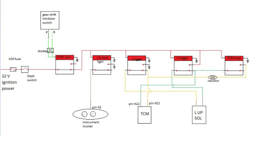
Actually it seems the TCM controls/switches both sides of the solenoid power, from the testing we've done. But we initially planned to switch both sides so we could close the loop of the TCM circuit (with a resistor in line) and have a separate power feed and earth for the solenoid. This way has the least chance of upsetting the computer.Leave a comment:
-
Well done MRW82. You have the concept exactly right. Your is obviously different to mine (early 120 with 1KZ), so the whole wiring system is different to mine. I have had a bit of a look see at the wiring diagram and from memory the TC activation was through the earth side?? But would have to go back to bet on it.
Anyway, very interested to see how you get on and how it goes.
As I said at the start, others will have a different take on what they want, I just did what I did because that suited me. Lots of different ways to control the lock up.
Incidently, mine is still going brilliantly, wouldn't be without it now and drive all the time with it locked.
Cheers, JamieLeave a comment:
-
Didn't get too far today as we done some more testing and found that the power to the solenoid from the TCM isn't 12 volts. Bugger. Ive tracked down a voltage regulator 5volt 3amp, but won't have it until later in the week. I will edit the diagram as to where it will go (+trigger relay power feed to switched side). Everything else should remain the same.
Bill the relays I was going to use are mini relays from jaycar, make sure they are 5pin/changeover relays. And the resistor I got is 6.8ohm 5amp with a ceramic heat sink on it.
I am actually now looking at getting some solder in relays and mounting them (and the resistor, diodes, regulator) onto a board, will be a lot neater and more compact to fit in a small mountable box (also from jaycar)Leave a comment:
-
MRW82
Hi Mark, Looks like you have been doing your homework. Looking good. Do you know whether you will be using the standard relays yet and also what size the resistor will be as I will have to get my bits down from Darwin. Thanks and cheers BillLeave a comment:
-
Here is the current plan of a wiring diagram, it is currently untested and may get revised if we come across something during the install.
i'll do a write up of how it works and why we done it this way once we know it works. Stay tuned.Leave a comment:
-
Had a good chat to my auto Leckie mate and have some good info to share shortly. It will hopefully get wired up this Sunday. There are a few modifications to my diagram and adding a couple of extra relays and a resistor to keep the TCM happy so it doesn't throw codes.Leave a comment:
-
Hi all, Where is everyone???? I'm lonely up here. Cheers Bill. Have a good weekend.Leave a comment:
-
Hi all, have just found this bit on the homemade TC lock up in my above note for the Pajero.
I have been feeling uneasy about that resistor generating a fair amount of heat when the ecu allows 12volt through it. Essentially the ecu acts as ground so if it normally would lock up 12volt will pass through the resistor.
To combat that i have added another relay that will bypass my wiring and render the gearbox in stock form when the ecu wants to use lockup. So essentially when my switch is on and the ecu wants lockup it locks through it's own process but as soon as it unlocks my relays kick in and keeps it locked up.
With the switch off the gearbox wiring is essentially stock.
So the resisitor essentially will never see 12volt but for the split second in relays switching power around. In this method i dont know if the relay is crucial but im leaving it there to avoid the ecu maybe throwing a code.
Hope it may help with the Prado, Cheers Bill.Last edited by chardo; 10-10-2014, 10:41 AM.Leave a comment:
-
hi Guys,
I've been away and missed a bit here. Just had a quick read through, but too tired to take it in properly atm. Quite interesting discussions going on. I'll have to tackle the info in a day or so when I get a mo and see whats going on.
Cheers, JamieLeave a comment:
-
MRW82
Hi mate, I am new at all this, but can you open this up. It is a photo of a home made TC lock up kit It also has a resistor needed to fool the computer into thinking its the solenoid. Can you let me know if you can open it. I have the photo in favourites, but don't know how to insert it here. cheers Bill.
http://www.4x4community.co.za/forum/...0&d=1340711782Leave a comment:
-
Bill, I've got the wholesale automatics wiring diagram and it only covers up to 03 (the 4 speed auto). Strangely, It does have a diagram for the 1kd but it is wrong colour wiring and wrong pin, maybe for a different market.Leave a comment:
- Please update your email address to ensure you receive our emails.
- Welcome to the updated Pradopoint. The private message system has been enabled.

Leave a comment: